
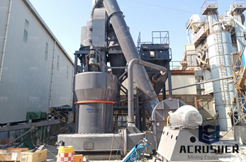
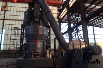
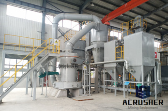
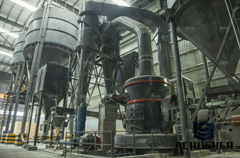
p id equipment symbol for a hammermill manufacturer Grasping strong production capability, advanced research strength and excellent service, Shanghai p id equipment symbol for a hammermill supplier create the value and bring values to all of customers.
 WhatsApp)
Click to print (Opens in new window) Click to share on Facebook (Opens in new window) Click to share on Twitter (Opens in new window) Click to share on LinkedIn (Opens in new window)
The Piping and Instrument Diagram (P&ID), based on the Process Flow Diagram (PFD), represents the technical realization of a process by means of graphical symbols for equipment and piping together with graphical symbols for process measurement and control functions.
Mar 08, 2013· Symbol is the basic notation to describe or represent a P&ID. To read and interpret piping and instrument drawing, the reader must learn the meaning of the symbol. We will discuss about the common symbols that are used to depict fluid process plant. In general all the symbols used in P&ID are as per ISA or ANSI standard.
A P&ID diagram with incoherent formats leads to confusion and misunderstandings on the part of process technicians. Based on the above reasons, a complete set of standards must be determined before the development of P&ID diagrams, either to create a P&ID diagram by hand or on a computer.
P&ID is sometimes referred to as a Piping and Instrumentation Drawing. These diagrams are also called flowsheets. P&IDs are used by process technicians and instrument and electrical, mechanical, safety, and engineering personnel. In both diagrams arrows show the flow of material and symbols show tanks, valves, and other equipment. The symbols ...
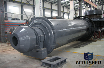
P Id For Iron Ore Crushing System. P id for iron ore crushing syste. AC from Zhengzhou Jinma Mining Machinery on p id for iron ore crushing syste. . or as request. Payment Terms LC,DA,DP,TT,Western Union,,negotiable . Ball mill grinding is the key equipment that repulverizes crushed materials. High Quality Food Industry Grade Conveyor Belt ...
Using Machine Symbols to Design P&ID From the P&ID examples below, you will see how to use the machine symbols effectively. There is a large piping and instrumentation diagram example gallery with more professional examples available to be downloaded.
Process & Instrumentation Diagram (P&ID) Purpose 1. To indicate the instruments or control devices attached to the process. 2. To indicate the control system architecture associated with the process. Howitisdone? Standard symbols and notations representing instruments or control devices are placed to the pipings and vessels.
P&ID schematics also show the instruments and valves that monitor and control the flow of materials through the pipelines. Process flow diagrams. PFDs show how industrial process equipment is interconnected by a system of pipelines. A PFD is more conceptual than a P&ID, and usually includes more annotations that display data.
Dec 27, 2019· Piping and Instrumentation Diagrams (P&ID) are schemes of pipelines, equipment, instrumentation, control systems, from a process system found in Oil Refinery, Chemical Plant, Paper Mill, Cement Plant, etc.. The symbols contained in P & ID represent equipment such as actuators, sensors and controllers.Process tools such as valves (valves), instruments, and pipelines are .

Hammer Mill P Id Symbols Dwg. Hammer Mill P Id Symbols Dwg Our company has been devoted to mining machinery for 40 years With its ingenuity quality intimate service and good reputation it has aroused the backbone of Chinese manufacture and won the praise of the global users
Hammermill. ® Paper for Life. ® Hammermill paper is scientifically designed and rigorously tested to perform at the highest level everytime. For over 100 years, we have been dedicated to helping people capture ideas, share thoughts, and show their work at its best at work, at home, and in school.
The table below contains some of the instrument abbreviations used in conjunction with P&ID symbols in instrumentation diagrams. I have dealt with some of them before but for the purpose of emphasis and completeness let us go through again. The list here is by no means exhaustive but it is a good starting point for beginners to P&IDs:
The symbols and identification contained in ISA-5.1 have evolved by the consensus method and are intended for wide application throughout the process industries. The symbols and ... 2.1.2 Process equipment symbols are not part of this standard, but are included only to illustrate applications of instrumentation symbols.
Sep 30, 2015· P&ID Symbols in AutoCAD P&ID or AutoCAD Plant 3D - Duration: 3:31. ... Lesson 2 - Autodesk Autocad P&ID Tutorial: Basic Of Equipment(Add New symbol To Tool palette) - .
and asks that they be addressed to the Secretary, Standards and Practices Board, ISA, 67 Alexander Drive, P.O. Box 12277, Research Triangle Park, NC 27709, Telephone (919) 549- ... 2.1.2 Process equipment symbols are not part of this standard, but are included only to illustrate applications of instrumentation symbols.
P&ID Symbols and Notation. As we all know that the industrial P&ID diagram comprised of specific symobols (P&ID Symbols) having specific shape special notation .In this article we will see different symbol and notations used to create a P&ID diagram as per industrial process .
The screenless hammer mill uses air flow to separate small particles from larger ones. It is designed to be more reliable, and is also claimed to be much cheaper and more energy efficient than regular hammermills. The design & structure of the hammermill is always determined by the end use. History
Like other specialized diagrams, P&ID's are comprised of standard shapes and symbols. There's a huge variety of symbols, depending on industry and manufacturer, so we've created this guide to feature the most popular P&ID symbols supported within our P&ID software and is standardized for best practice across the industry.
Dec 21, 2017· A piping and instrumentation diagram (P&ID) is a graphic representation of a process system that includes the piping, vessels, control valves, instrumentation, and other process components and equipment in the system. Downloadable pdf of Valve, Actuator and other popular P&ID symbols.
The Working Principle of Hammer Mills (Step-by-step Guide) A hammer mill is an essential machine in the pharmaceutical and food processing industries. You can use it to crush, pulverize, shred, grind and reduce material to suitable sizes.
P&ID symbols and level of information available on P&ID may change from company to company, but more or less they provide similar information. What P&ID or PFD symbol is? P&ID symbols are a graphical representation of physical equipment that installed on the field.
EQUIPMENT in P&ID. Equipment is the main items shown in a P&ID to perform the process required treatment. The plant equipment is shown in the P&ID by an icon showing the equipment in basic manner. Usually they are identified by a name and unique tag (Unique identifier that is assigned to a field device, skid or equipment).
A piping and instrumentation diagram (P&ID) is defined as follows: A diagram which shows the interconnection of process equipment and the instrumentation used to control the process. In the process industry, a standard set of symbols is used to prepare drawings of processes.
WhatsApp)